OHM’s law is fundamental to resistance welding. This law states that, “If the voltage remains constant, the current flowing through any circuit is inversely proportional to the resistance in that circuit.” E=IR. E=volts, I=current in amps, R=resistance in ohms.
The principal requirement for resistance welding is the generation of heat. The formula for power dissipated in an electrical circuit is: P=I²R. P=power in watts, I=current, R=resistance. The current flow in amperes is the same in all parts of a single path circuit regardless of the resistance from point to point. However, the heat generated at a point will be directly proportional to the resistance at that point.
In resistance welding, the work pieces are designed to have the most resistance and therefore the most heat, at the point where the weld is desired. The connecting wires are designed to have very low resistance while carrying the same amperage. Consequently, the connecting wires remain relatively cool.

At points A and C of Figure 1, the electrode to wire and electrode to slug resistance is kept to a minimum through the use of a copper tungsten material, which provides both low electrical resistance and good physical wear resistance.
At point B of Figure 1, a chisel point cut into the wire provides the initial point of high resistance that results in the point of highest heat.
The heat energy generated in the junction being welded and the connecting electrodes is expressed by Joules Law as: W=I²RT. W=heat energy in watt-seconds or joules, I=current in amperes, R=resistance in ohms, T=time of applied current in seconds.
Typically, a substantial amount of heat is dissipated in the D.C. resistance in the transformer, in all connecting joints, buss lines to electrodes, electrodes and interfaces, as well as A.C. inductive losses in the transformer. That is, heat is generated and lost at many points other than the junction itself.
With the loss effect added, the heat energy formula becomes: H=I²RTK. K=factor representing heat losses.
The losses are caused primarily by radiation from the fixtures and objects to the surrounding air. Because these losses are not easily controlled, the time of application of the current is an important factor.
Since the heat generated at a point is proportional to the square of the current, neglecting losses, a doubling of the current will quadruple the heat produced over a given period of time. A change of heat generated may be obtained either by a change of current level or by a change in time duration. However, heat transfer through the metal surrounding the junction takes a finite amount of time. As a result, for the development of a proper-sized weld nugget the time duration cannot be shorted below a minimum, regardless of the increase in current. The usual effect of high current with insufficient time duration is heat generation so rapid that burning takes place at the contact surfaces.
The weld pressure does not enter directly into the formula just discussed, but it does have a direct effect on welding current since it affects the resistance at the junction of the two work pieces.
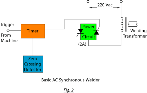
A typical example is shown in the block diagram of Figure 2. It consists of a power circuit capable of switching both halves of the AC line voltage (Fig. 2A), a zero voltage detection circuit for synchronizing switching of the power circuit, a timing circuit to trigger the power circuit for the desired amount of weld time, and a welding transformer to convert high voltage at low current to low voltage (commonly 2 to 6 volts) at high current.
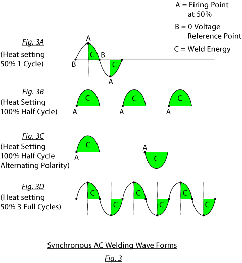 The output of a synchronous AC power supply is normally adjustable in three ways, as depicted in Figure 3 (below):
- Heat Setting – Controls the percentage of each half cycle line voltage applied to the weld transformer, as referenced from the zero crossing point of the AC voltage. (Figure 3A)
- Half or Full Cycle – Sets the power supply to deliver consecutive half cycles of line current of the same polarity or of alternating polarity. Full cycle will deliver at least one full cycle of line current. (Figures 3B and 3C)
- Number of Cycles – Sets the number of cycles of line current delivered for every welder firing. (Figure 3D)
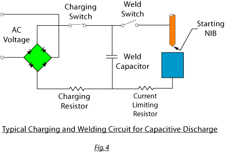
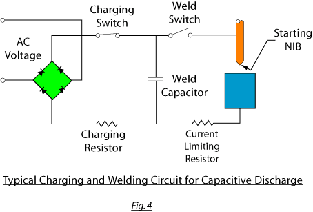 A typical circuit is shown in Figure 4 (below). The capacitor(s) is charged by direct current from a rectifier or generator. This welding energy is stored at from 50 to 300
VDC and later discharged through either mechanical or electrical switching methods into the primary of a high current welding transformer.
The controls for this weld power supply are:
- Voltage Applied – An adjustment to voltage stored in the capacitors.
- Amount of Capacitance – An adjustment of the number of capacitors.
- Weld Current – An adjustment of the taps on the welding transformer to vary the voltage on the secondary winding.
DUMET AND BARE DUMET.
Oxidized dumet consists of copper clad nickel iron that is passed through a heating process which causes copper oxide to form on the copper clad surface. This dumet is normally used in applications employing some form of controlled atmosphere in the sealing process.
The borated dumet also utilizes copper clad nickel iron that is oxidized. However, after oxidation the dumet is heat treated with a borax solution to form a surface of sodium tetraborate that facilitates glass sealing in flame-type processes.
CCFE (copper clad iron steel wire) comes in various sizes and a range of 20% to 88% conductivity. The conductivity of pure copper is considered 100%.
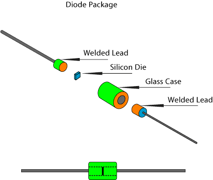
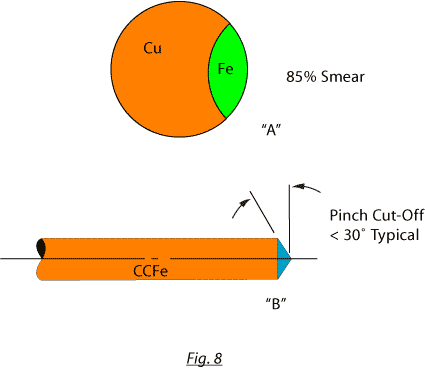
To manufacture a welded dumet to CCFE assembly, as shown in Figure 6, it is necessary first to cut the dumet slug to the proper length. This cut, made properly, requires that both ends of the cut slug be free of burrs and that a smear of copper be carried across approximately 75% of the surface opposite the weld as shown in Figure 8A, and that the sealing surface of the dumet be free of any scratches or marks that could affect the glass-to-metal seal. The CCFE wire is then cut to length, forming a chisel-type point as shown in Figure 8B. This chisel point is cut at various angles, typically <30%, to provide a relatively high resistance point at the weld junction.
The dumet slug and CCFE wire are brought together under pressure and the welding current is applied through a set of clamp-type jaws on the CCFE wire and through an electrode that contacts the dumet slug on the side opposite the weld, as shown in Fig 1. When current passes through the work pieces, the relatively high resistance of the CCFE/Dumet interface causes the junction to heat rapidly as the welding pressure forces the two work pieces together, welding the two metals. The actual weld process on DO 41 and DO 35 welds takes from 3 to 8 milliseconds, depending on material, conductivity, and wire size.
Resistance welding produces no arc which could cause the rapid oxidation of the powdered tantalum metal slug. It also minimizes the effects of both oxygen and nitrogen that could cause the formation of oxides and nitrides in the weld junction and the area surrounding the weld. Handling, straightening, and cutting of tantalum requires care to avoid the adherence of lubricating oils that would degrade the finished capacitor.
Tantalum is extremely abrasive. It requires that cutting be done with tungsten carbide tools and that the dies in a rotary straightener be made either of ceramic or nylon to prevent premature wear. Because tantalum is so abrasive, the tantalum dust that accumulates on welding machines must be removed by daily cleaning to prevent excessive wear of moving parts.
Arc initiation, arc time, and welding impact are controlled and synchronized automatically. The weld power supply usually is of the capacitive discharge type. The welding impact (forging force) is applied by electromagnetic devices, electromechanical devices, cam-actuated direct drive, springs, or gravity.
The heat generated is intense but extremely brief in time, and is closely localized to the junction. It enables the percussive welding of a small component to a larger one, and of dissimilar metals that differ considerably in electrical resistivity and melting temperature. The electrical resistivity of the parts being welded does not noticeably affect the amount of heat generated at the junction. The arc supplies the heat for welding of the metals.
The work-holding clamp, jaws, or chuck of the welding head need not be a good electrical conductor, as in resistance welding, because the amount of current passed is comparatively small and the duration of current flow is extremely brief. The work-holding clamp material is usually selected primarily for strength and wear resistance. Hardened steel is commonly used.
to terminals of electrical and electronic components where a reliable joint is needed to withstand shock, vibration, and extended service at elevated temperature. It is used commonly in the welding of copper to molybdenum for use in the manufacture of power rectifiers, in making telephone and electrical devices, and for attaching large-area contacts to switch components.
Percussive welds can be made a few thousandths of an inch away from glass seals or other heat-sensitive materials without damage to these materials, because the total heat generated is small and can be localized. Percussive welding can be massive or it can be thin metal, as in a capacitor cathode can, or stranded wire, or solid wire. Flat work pieces of any shape can be percussively welded to mating flat surfaces with the aid of an arc-starting nib.
Capacitor-discharge percussive welding can be used to butt weld wires of similar diameters or of greatly different diameters. For some metals, wire diameter can be as small as .005 inches.
Heat treated, cold worked, or prefinished metals are unaffected by the heat of percussive welding, because the heat-affected zone is very shallow, usually only a few thousandths of an inch.
Cleaning is not critical to the production of sound percussive welds because at least a thin layer of metal is melted from each work piece and expelled from the junction.
Almost any pair of like or unlike metals or alloys can be joined by percussive welding. Work pieces of widely dissimilar composition, melting temperature, electrical conductivity, and thermal conductivity can be readily welded together.
Metals easily welded include copper alloys, aluminum alloys, nickel alloys,
low-carbon steels, medium-carbon steels, and stainless steels. Various combinations of these alloys also have been welded.
Copper may be percussive welded to molybdenum. Although true welds between these two metals at one time were considered impossible because of mutual insolubility, tests have shown copper penetration of .0004 inches into molybdenum at the weld junction.
Low-voltage capacitors that have high capacitance commonly are used in power supplies for capacitor-discharge percussive welding. The capacitor is charged by direct current from a rectifier or generator, and the welding energy is stored at 50 to 300 VDC and later discharged to make the weld.
The relatively low voltage makes this type of power supply appropriate for use with bench- mounted welding heads since the operator is not exposed to extremely high voltage.
The high-voltage capacitors that have low capacitance are also used to supply power for capacitor-discharge percussive welding. They function electrically the same as the low-voltage capacitors, but store the welding energy at 1000 to 6000 VDC.
High-voltage capacitors can produce a more uniform arc discharge, and the use of
this type of power supply is one way of avoiding the need for the arc-starting nib. The high voltage allows more latitude in controlling the operating variables of the welding process. However, it is more difficult and costly to provide operator protection against voltages that are often above 1000 volts.
A typical capacitive discharge welding circuit is shown in Figure 4 (below).
Factors affecting arc time include the work metal or combination of work metals, the mass of the moving work piece and moving parts of the machine, nib dimensions, welding voltage and current, welding force and synchronization of arc initiation with the application of welding force.
The shortest arc time that will permit the formation of a sound metallurgical bond with some penetration of the work piece is generally used to minimize heating effects on adjacent areas of the work pieces. Typical arc times in percussive welding are from .5 to 1.5 milliseconds.
Because of the short arc time, the heat-affected zone is very shallow. For capacitor- discharge welding, it is often only about .0015 to .005 inches. In percussive welds between metals that have widely different melting temperatures, the heat-affected zone may be only a few millionths of an inch in the higher-melting temperature metal and .015 to .025 inches in the lower-melting temperature metal.
The amount of energy used in making a percussive weld depends on the cross-sectional area of the junction, the properties of the work metal or metals and the depth to which metal is melted into the work pieces.
Welding current, or the arc-discharge pattern, in percussive welding varies with the application and is not usually measured. However, current peaks of 400 amps are equivalent to nearly 1/2 million amps per square inch on a .032 inch diameter wire.
Polarity is of no consequence in making percussive welds between work pieces made of the same material and having the same cross-sectional area, but can drastically affect the welding of dissimilar metals or materials of different cross-sectional area. In the welding of metals of different melting points, the metal having the highest melting point or greatest cross-section area is normally given the POSITIVE polarity.
The selection of polarity is of special importance in the percussive welding of unlike metals that differ greatly in melting temperature and is used to minimize the depth of heat-affected zones in the lower melting point metal.
The temperature difference of the two work pieces relative to polarity is explained by the effect of the electron bombardment of the anode during the arc discharge. This electron bombardment of the anode causes the anode to become intensely hot, attaining a temperature of approximately 3600° Kelvin (3326° centigrade). Although the temperature of the cathode is much lower than this, it will still be hot enough to melt most metals.
To produce good welds, the welding force must be adjusted empirically until the proper weld quality is achieved. Welding force can be supplied by an electromagnet, gravity, a cam-actuated direct drive, or a spring, depending on the type of welding machine and parts being joined.
In high-voltage start, the arc is started by applying to the work pieces a direct current voltage, which is high enough to overcome the resistance of the air in the gap between the work pieces as one moves toward the other. The air is ionized and the flow of welding current is started.
In the RF-START method, the process involves superimposing a high-frequency, high- voltage alternating current on low-voltage direct current across the gap between the work pieces. The high-frequency field ionizes the air in the gap producing an arc, and the low-voltage direct current from the capacitors maintains the are. This arc-starting method is used on some low-voltage capacitor discharge percussive welders. It eliminates the need for preparing a nib on one of the work pieces
In the third method, the STARTER NIB is prepared, as shown in Figure 5A, on one of the work pieces by cutting it at an angle, or in the shape of a chisel tip. The low-voltage direct current supplied by the capacitors, when the two work pieces come together, will create enough heat to melt the nib, which is heated so rapidly that an explosion of molten particles occurs. This explosion helps to further form the electric arc, which then spreads progressively over the junction.
These four parameters interact to determine the arc duration and the timing with respect to arc discharge. The rapid approach of the work pieces serves to trigger the arc discharge.
Usually, conditions are adjusted to give the shortest arc time that will permit consistent production of welds having the desired properties. If the work pieces are forced together too early, the arc is extinguished before the work surface of both work pieces have melted. If the impact is delayed too long after arc initiation, the melted interfaces may solidify, not allowing the expulsion of oxides and excess molten metal.

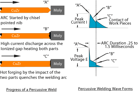
As shown at the upper right of Figure 5, peak welding current is achieved almost immediately on arc initiation (point A). The current then decays rapidly during the arc discharge (point B). The current increases to a secondary peak on contact of the work pieces (point C) because of the sudden drop in electrical resistance, and then tapers off to zero in an additional 3 to 5 milliseconds.
As shown at the lower right of Figure 5, voltage across the weld decreases very rapidly (point A) to a fraction of its initial open-circuit value when the arc is initiated by the close approach of the moving work piece to the stationary work piece. The voltage then decreases less rapidly (point B) as the arc discharge continues. The arc is extinguished on contact of the work pieces (point C). After a typical arc time of .25 and 1.15 milliseconds, the voltage decreases almost instantly to nearly zero.
Any one of the three starting methods mentioned in the arc starting section can be used to start the flow of welding current. However, the most common methods are NIB and RF START. Because of the low melting point of zirconium copper relative to the melting point of the molybdenum, as this weld takes place, there is a rather large amount of zirconium copper expelled from the weld junction.
This weld splatter can cause trouble. The problems are excess copper on the surface of the moly slug and contamination of the work area and the machine tooling that could prevent consistent welding of a sequence of parts.
One solution is to weld in an oil bath to solidify and carry away the hot copper particles as soon as they leave the weld area. This oil bath will also help control the weld process by forming a reduced oxygen atmosphere at the time of the weld.
When oil is used to contain the weld splatter, NIB START is the most acceptable means of starting the weld. The RF START method is not acceptable for use with oil because the dielectric strength of the oil will affect the timing of the high-frequency discharge and prevent consistent welding of the work pieces.
The energy necessary to make the weld is stored in electrolytic capacitors that are charged by an adjustable DC power supply via a current-limiting resistor to a preset voltage. The charged capacitors are then switched to the primary of a welding transformer. The secondary of the transformer is connected to the work pieces where the weld is completed.
The resistance welding process is well suited for this type of weld because tantalum, when heated, is highly reactive to oxygen and other gases and can actually be ignited by an electrical arc. Resistance welding produces no arc which could cause the rapid oxidation of the powdered tantalum metal slug. It also minimizes the effects of both oxygen and
nitrogen that could cause the formation of oxides and nitrides in the weld junction and the area surrounding the weld.
The tantalum anodes are handled very carefully to prevent physical damage and contamination from oils. They are fed from a vibratory feeder bowl through a stainless steel feed track into hardened steel injectors and pin feed units to tungsten copper welding jaws. The tantalum riser wire is fed from the wire spool into a rotary wire straightener. Nylon is used in the straightener dies because of the highly abrasive nature of tantalum. After straightening, the wire is measured and fed into a tungsten carbide knife and die, cut and positioned in the tungsten copper weld jaws. Because tantalum is so abrasive, the dust that accumulates on welding machines must be removed by daily cleaning to prevent excessive wear of moving parts.
After positioning in the weld jaws, both pieces are brought together and pressure is applied by pre-loaded spring plungers. The capacitors are switched to the primary of the welding transformer and high current is then passed through the two work pieces, making the weld. The current and time of the weld varies with different sizes of wire and anode density, but a typical current would be approximately 173 amps peak for about .005
seconds (5ms). The high current for this short time produces very intense heating of the relatively high resistance interface of the two work pieces. This causes the rapid forming of a molten pool of tantalum that becomes a localized weld knot. The welder has switch- selectable capacitor banks with a fully-adjustable DC power supply that allows fine adjustment to the weld energy.
The majority of our work has been done with cylindrical anode pellets, but we also have experience with rectangular anodes. The range of sizes of cylindrical parts is diameters from 0.8mm to 3.5mm and lengths from 1.95mm to 7.4mm. Typical rectangular parts are 2.30mm x 4.00mm x .75mm. Wire diameters are .3mm to .4mm with a length of 12.7mm.
Smaller sizes of anode pellets can possibly be welded with modifications to tooling and adjustments to the welder power supply. The powder density of these anode pellets varies, but presents no real problem welding as long as they are durable enough to withstand the
vibratory bowl feed and subsequent weld jaw chucking without damage. CIT would test pellet density prior to accepting any order for welding equipment. Please note: All of the welding we have done up to this time was accomplished on anodes that have been FORMED and SINTERED ONCE prior to welding. After welding the completed anode assembly with riser wire, it undergoes a SECOND SINTERING. If you have any questions or need additional information, please contact us.
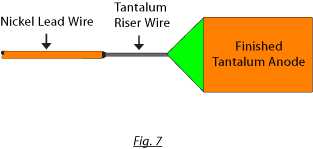
This weld, shown in Figure 7, is used commonly in the fabrication of tantalum capacitors for the connection of the nickel lead wire to the tantalum anode riser wire. Resistance welding can be used since tantalum and nickel provide a relatively high resistance point at the work piece interface. However, the short anode riser wire, and the tantalum pentoxide coating that is on the surface of the riser wire dictate that a lap weld rather than a butt weld be made.
Using percussive welding to weld the riser wire to nickel lead wire allows the automatic feeding of the loose anodes via a vibratory bowl feeder into an automatic welding machine. The relatively high voltages and low currents typical of percussive welding permit the welding jaws gripping the short anode riser wire to be small sized and to be made of material that exhibits a long wear life, such as tungsten or tool steel. The high voltage of the percussive weld easily overcomes the insulating properties of the tantalum pentoxide that coats the riser wire and minimizes the effects of slightly higher resistance at the jaw clamp to riser wire interface.
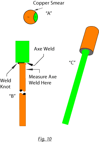
Smear
The copper cladding that is dragged across the cutoff end of the dumet during the cutting of the slug (See Figure 10A below).
Weld Knot
The weld fillet around the wire to slug interface (Figure 10B).
Axe Weld
An incomplete weld fillet between the slug and tail wire that appears to have been cut by an axe (Figure 10C).
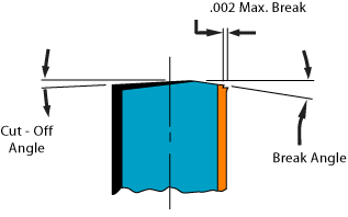
Breakoff / Cutoff (BO/CO)
Two effects of the cutting of the dumet slug. The breakoff is the uncut portion of the slug. The cutoff is the smooth cut.
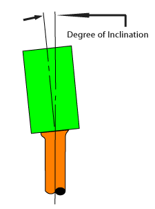
Tilt
The degree of inclination of the slug to the wire.
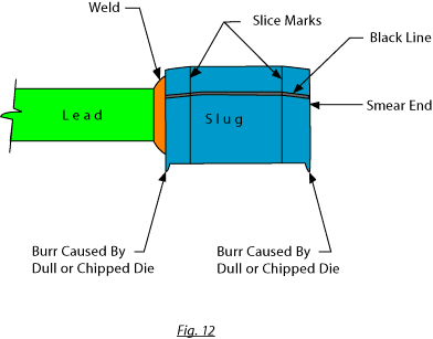
Burr
The deformed metal at each end of the cut slug caused by wear in cutter tooling.
Tir (Total Indicated Runout)
The measure of concentricity between the wire and the slug as indicated

Starter Nib
The small point cut onto one work piece that is burnt off by the initial welding current and used to start the welding arc.
Resistance Welding
Advantages
This technique allows for very small and strong welds of similar metal such as CCFE to dumet. Welding speed in excess of 500 PPM.
On large diameter work pieces, multiple AC line cycles can be used to heat work more slowly.
Welding voltage is low:
1.56 V AC or DC.
Disadvantages
Work pieces need to be prepared with a relatively high resistance point at weld junction.
Welding currents are high, requiring very tight low-resistance weld jaws that wear more rapidly due to material pressure and heat.
Percussive Arc & RF “Start” Percussive Welding
Advantages
Welding of dissimilar metals, copper to steel.
These welders typically have a long wear life for welding jaws due to very short relatively low current welding pulse.
Welding of metals with high melting point such as tungsten, moly.
Disadvantages
Welding is typically more dirty and less smooth than Resistance welding.
With nib start percussive arc welding, a starting nib must be cut onto work pieces.
With “RF” start percussive arc welding, work pieces must be free of oil or dirt.
Welding voltage is high: 50 to 300 VDC.


Comments are closed.